Latest Post

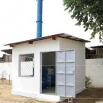
Containerised Biohazard Incinerator
BIOHAZARD DISPOSAL: CONTAINER
GENERAL INCINERATOR, IDEAL FOR INCINERATION OF VARIOUS TYPES OF WASTE, FULLY CONTAINERISED IN A 20 FT CONTAINER, TO INCLUDE BUILT-IN FUEL TANK AND GENERATOR.

mobile Incinerator
TECHNICAL SPECIFICATIONS: COMBUSTION CHAMBER VOLUME (M3); 0.54 m3. SUGGESTED BATCH SIZE: 60 KG, BURN RATE: 69 KG PER HOUR, AVERAGE FUEL CONSUMPTION 13 KG PER HOUR, OPERATIONAL TEMPERATURE: 950-1320 CELSIUS, GAS RETENTION IN SECONDARY CHAMBER 0.5 SECS, WITH TEMP. MONITORING , AVERAGE ASH RESIDUE: 3%, THERMOSTATIC DEVICE: YES,
Incinerator for hospital
DESCRIPTION OF WORKS
The services and equipment described in this specification comprises the supply, delivery, installation, testing and commissioning of an incinerator and the associated accessories including oil installation at the Hospital.
The tenderer is to ensure that the equipment they proposes to supply is from a reputable manufacturer with full spare back-up and can be serviced and maintained by locally available personnel and is not of such a nature as will require overseas expertise to attend to its maintenance and servicing.
The tenderer shall include for all items not called for in this specification but which are necessary for the completion, safety and satisfactory functioning of the works. The installation and components are to comply with all the requirements of the local authority’s bye-laws, regulations of water and fire brigade authorities and the latest Kenya Bureau of Standards, British standard specifications and codes of practice or equivalent approved international standards and National Environment Management Authority (NEMA) Regulations.
The tenderer shall be deemed to have visited the site to ascertain the site conditions.
1.0.3. SCOPE OF WORKS
The works comprise the supply delivery, installation, testing and commissioning of 1No. Incinerator, complete with associated accessories including flue and oil installation. The oil installation shall comprise bulk oil storage tank, daily oil tank, transfer hand fuel pump and the associated pipework. The burning capacity of the incinerator shall be 75kg of hospital waste per hour as NU-WAY LTD models or equal and approved.
The incinerator will have a primary and a secondary combustion chamber, temperature indicators, burners operation and safety controls and a suitable flue (chimney).
1.0.4 COMMENCEMENT OF WORK
The tenderer in submitting his tender shall be deemed to have included for commencing any necessary work and other expenses which may be incurred by the tenderer including travelling to site. No claims will be allowed for the traveling or other expenses which may be incurred by the tenderer.
E-1
1.0.5 CLIMATIC CONDITIONS
The following climatic conditions apply to the site of the contract works and plant, equipment, apparatus and installation shall be suitable for these conditions.
| CLIMATIC CONDITIONS | nairobi |
|
Maximum Design Temperature
Minimum Temperature
Relative Humidity
Altitude
Longitude
Latitude |
27.7˚C
10.8˚C
41 – 59.7%
1624M ASL
36˚ 55’E
01˚ 19’S
|
Heavy rains fall during certain periods of the year and the tenderer shall be deemed to have taken into account of this fact both in his prices and planning of the execution of the works.
1.1.0 THE EQUIPMENT AND PLANT
1.1.1 Incinerator
The incinerator shall have chimney, castable high quality refractory lining and incinerator shell, perforated blind for the primary and secondary combustion chambers and air circulation system.
The incinerator shall also have the following:-
- Ash door
- Primary and secondary burners and fans
- Temperature indicator devices
- Electrical wiring from the local isolator
- FD fan
- Air receiver
- Air ductwork complete with air dampers
- Pressure and temperature gauges
- Fully wired control panel
The bulk oil storage tank shall have a capacity of 10,200 litres and be placed at 0.5m above ground on a firm concrete cradle, complete with the following:-
- Drain pipe
- Vent pipe
- Oil level indicator
- Access ladder to the top of the tank
- Coating of the tank with at least 2No. coats of bituminous paint
- Manhole cover complete with a gasket
- Dip stick
- Any other necessary accessory.
E-2
The daily oil tank of capacity 1,800 litres and size 1220x1220x1220mm pressed steel tank high shall be placed 2.5 metres high above finished floor level on a steel stand, firmly secured on the ground and the steel members to be bolted. The daily oil tank shall have an oil level indicator, access manhole, washout, overflow, inlet and outlets connections and gate valves.
The interconnecting pipe of 50mm diameter between the two tanks shall be class ‘C’ black mild steel pipe, complete with a 50mm diameter strainer. The burner fuel supply pipe from the daily tank shall be a 25mm diameter class ‘C’ black mild steel.
The following shall also be supplied
- 25mm diameter fire valve
- 25mm diameter high capacity strainer
- heating tap along the burner supply pipe, 25mm diameter
The burner supply pipe shall have 25mm thick fibre glass insulation and finished with gauge 20SWG galvanised steel sheet.
The tenderer shall provide all the necessary controls for proper safety and satisfactory working of the installation.
1.1.1 BURNER
The burner shall be suitable for 35 sec redwood No. 1 scale fuel oil. It shall be robust in construction and be manufactured in cast iron or other suitable materials complete with mounting plates. It must be easily mountable and demountable for ease of cleaning and maintenance. The burner shall have an adequate supply of oil which will readily ignite and burn in a safe manner. Adequate provision shall be provided to prevent any solid matter in the oil, or any matter that may separate out from the oil from damaging any components or chocking of any orifices or valves. The free filtering area should be sufficient to ensure that the filter does not need dismantling for cleaning more often than once a year. The burner shall have flame supervision by photo-electric cell with synchronous sequence controller for automatic start up, running and shut-down of the burner.
The burner shall have all the necessary controls e.g.Solenoid valves, ignition controls, photo electric cell fuel safety controls, low pressure fuel supply cut-off etc.
The burner shall conform to BS 799: part 3 and 6 1981 or any other relevant British standard.The burner shall be as NU-WAY models or equal and approved.
1.1.2 CONTROLS
The incinerator shall operate in an automatic manner with all the necessary controls. These controls are to include safety elements such as flame failure unit, pilot lamps, fuses, starters, overload contactors, ON and OFF switches for burners and fans, combustion chamber temperature indicators for primary and secondary chambers etc.
- i) Electric ignition switch ‘ON’ before the oil is supplied
- ii) Delayed return to re-start position to allow purging
iii) Re-start after temporary electric supply failure
- iv) Positive safety lock-out in case of flame failure from whatever cause.
- v) Red signal light on control panel to indicate safety lock out
- vi) Photo electric protective cell as flame failure device.
The controls shall be mounted on suitable control panel to be installed in a position easy to read and control from the charging door side of the incinerator.
The control panel shall be fabricated from anodized, 16SWG, mild steel sheet.
E-3
1.1.3 FLUE (CHIMNEY)
A flue chimney, 15,000mm long and 560mm diameter shall be constructed from steel sheet, complete with lagging, damper and rain water protection cone. The chimney shall be lined with castable grade diatomaceous concrete mixed with high alumina cement in accordance with BS 4076: 1989.
The damper will control the closing of the door to not less than 85%. The stack is to allow fresh air at the stock’s base so that the flue gases are discharged at not move then 4000 C and that the discharge conforms to the British Clean Air Act, the National Environment Management Agency (NEMA) Act or other relevant acts. .
1.1.4 POWER SUPPLY
The sub-contractor shall supply equipment which are suitable for running on a 415V, 3 phase, 50HZ or 240V, single phase, 50HZ electric power supply.
1.1.5 OIL STORAGE AND SUPPLY
The system shall consist of a bulk oil storage tank, daily tank, transfer hand fuel pump and associated pipe work. Oil from the bulk storage tank will be delivered to a high level daily tank situated in the incinerator room by use of a transfer hand pump and automatic electric pump.
1.1.6 SPARES AND MANUALS
The tenderer is to submit with his tender a list of recommended initial stock of spares together with their prices. A part from the burner spares mentioned here below, the spares prices are not to be included in the main summary of prices schedule but is to be separate and are meant to be ordered later if and when it becomes necessary and convenient to the client. The burner spares whose prices are to be included in the main summary of prices schedule (BQ) are:-
- i) Set of safety controls
- ii) Solenoid valve
iii) 1No. Oil ignition system
- iv) Photo-electric cells
Two sets of operating and maintenance manuals (both for the incinerator and burners) must also be supplied. This include two sets of control schematic diagrams for all the controls and wiring.

organic and hazardous waste incinerators
- Diesel incinerator.
- 25Kg/h. It will have mainly paper, cardboard and food, though also it will incinerate medical waste. So the incinerator shall be able to handle organic and hazardous waste.
- Spare parts for one year.
- The design should prevent any release of polluting substances into soil, surface water and groundwater.
- Combustion zone has to reach at least 860 degrees under the most adverse conditions with at least 6% oxygen. Since it will treat hazardous and organic waste, temperature has to reach at least 1100 degrees for at least 2 second.
- Flue gases must be cooled to 200 degrees or lower before flue gas treatment. The flue gas cleaning equipment maust be at least two-field electrostatic precipitator/ESP, dust <30mgNm3.
- Thermal efficiency not less than 85%.
- It should be equipped with filter to reduce and contain pollutants from organic and medical waste.
- Easy to operate for almost unskilled workers.

The medical waste incinerator
Electrical safety: The medical waste incinerator shall meet the requirements of IEC 61010-2-040, UL 61010A-2-041, or an equivalent electrical safety standard; as weil as the
electromagnetic compatibility requirements under EN 61326:1997 or equivalent standard.
Physical: Safety Belts, pulleys, chains, gears and other rotating parts as well as sharp edges, located where persons come in close proximity to them, shall be enclosed or guarded
to protect personnel. High-temperature surfaces and piping located where they could endanger personnel or create a fire hazard shall be covered with insulation
Noise level The noise level at 305 mm from any incinerator component shall not exceed 85 dBA.
Controls and instrumentation: The medical waste incinerator shall include control equipment and instruments, controls for burners and fans, time clocks, reJays, operating switches, indicator lights, gauges, motor starters, fuses, alarms, and circuit elements of the control system, and other controls and instruments necessary for operation of the incinerator.
The operation and regulation of the medical waste incinerator shall be done from a central console. The console shall include a visual graphic (screen) and computer recording to automatically monitor and record dates, time of day, batch number and operating parameters The medical waste incinerator shall include continuous online monitoring for combustion control including temperatures in both chambers, oxygen content, CO, C02, total organic carbon (TOC), moisture, and particulate matter (total dust) in the gaseous emission, measured
at every one minute interval or less
The control system shall include an emergency shut-down switch or button. The system should be protected against the effects of electrical short circuits
The control system shall prevent waste charging, if continuous loading, if the primary and secondary chambers are outsfde of their specified temperature ranges, and in the event of unsafe conditions#including failure of the combustion air fan, ID fan, or recirculation pump; and abnormal conditions at the air pollution control devices
Automatie control circuit systems and manual switches shall be interlocked to prevent hazardous conditions or the discharge of toxic air pollutants above the specified limits. The control system shall be able to use proportional control or other effective control algorithm to maintain the operating conditions specified herein.
Temperature measurement: The medical waste incinerator shall have an indicating recording pyrometer for measuring incinerator temperature with a range at least from O to 1315°C accurate to within ± 1% of range
The medical waste incinerator shall have thermocouples to measure gas temperatures and control burner operation, suitable for temperatures up to 1260°C and accurate to within 0.5% of the operating and indicating temperature range
Display indicators Temperature and other key parameters shall be readable by normal vision from a distance of 1.00m
Other indicator displays: Displays shall be able to indicate: operation in progress, end of cycle or fault conditions
lndicators for time: Error shall not exceed 1% of the indicated time in hours or minutes as applicable Fault condition In the event of a failure that prevents the completion of the process, the
controls shall be able to show a visual indication of failure and an audible alarm
Air pollution control where the medical waste incinerator is equipped with air pollution control devices, including de-dusting equipment and additional pollution reduction equipment, it shall be sufficient to meet the air emission limits specified in these specifications.
The following de-dusting equipment are acceptable: Fabric filters Operating < 260°C High temperature ceramic filters Cyclones
Electrostatic precipitators at 450°C
High performance adsorption unit with activated charcoal
The following additional emission reduction equipment are acceptable: Catalytic oxidation Gas quenching Catalytic oxidation
Catalyst-impregnated fabric filters Wet scrubber with lime solution
Dry scrubber with mixtures of activated carbon, lime, limestone Moving bed and fluidized bed reactors
Fixed bed reactor with activated carbon
Entrained flow or circulating fluidized bed reactor with activated carbon/lime or limestone followed by fabric filters
A ir emission limits: The medical waste incinerator shall be able to meet the follow ing air emission limits*, * *:
DAILY AVERAGE VALUES :
Total dust: 10 mg/m3 Carbon monoxide: 50 mg/m3
Gaseous and vaporous organic substances, expressed as total organic carbon: 10 mg/m3 Hydrogen Chloride: 10 mg/m3
Hydrogen fluoride: 1 mg/m3 Sulphur dioxide: 50 mg/m3
Nitrogen monoxide and nitrogen dioxide, expressed as nitrogen dioxide: 200 mg/m3
10-MINUTE AVERAGE VALUE:
Carbon monoxide: 95% – 150 mg/m3
HALF-HOURLY AVERAGE VALUES:
Total dust: 100% • 30 mg/m3, 97% – 10 mg/m3
Carbon monoxide: 100% – 100 mg/m3
Gaseous and vaporous organic substances, expressed as total organic carbon: 100% ·20 mg/m3, 97 % • 10 mg/m3
Hydrogen chloride: 100% – 60 mg/m3, 97% – 1O mg/m3 Hydrogen fluoride: 100% – 4 mg/m3, 97% –
2 mg/m3
Sulfur dioxide: 100% – 200 mg/m3, 97% • 50 mg/m3
Nitrogen monoxide and nitrogen dioxide, expressed as nitrogen dioxide 100% – 400 mg/m3, 97% – 200 mg/m3
AVERAGE VALUES OVER A SAMPLJNG PERIOD >6 HOURS TO 8 HOUAS:
Dioxins and furans: 0.1 ng l TE0/Nm3
AVERAGE VALUES OVER A SAMPLING PERIOD >30 MINUTES TO 8 HOURS:
Cadmium and its compounds: Total 0.05 mg/m3 Thallium and its compounds : Total 0.05 mg/m3 Mercury and its compounds: 0.05 mg/m3 Antimony and its compounds: Total 0.05 mg/m3 Arsenic and its compounds: Total 0.05 mg/m3 Lead and its compounds : Total 0.05 mg/m3 Chromium and its compounds: Total 0.05 mg/m3 Cobalt and its compounds: Total 0.05 mg/m3 Copper and its compounds: Total 0.05 mg/m3 Manganese and its compounds: Total 0.05 mg/m3 Nickel and its compounds: Total 0.05 mg/m3 Vanadium and its compounds: Total 0.05 mg/m3
Standard conditions defined as T = 273°K, P= 101.3 kPa, 11% 02, dry gas
Third Party Test Results: A copy of test results from stack sampling and analysis of air emissions from an incinerator of the same modal and capacity burning typical medical waste shall be provided and in compliance with EU DIAECTIVE 2000/76/EC. The tests shall be conducted by an independent Third Party duly accredited and certified. The test report shall
include concentrations of 17 congeners of 2,3,7,8-TCOO/F, corresponding detection limits, Toxic Equivalent (TEQ) using 1-TEF as well as TEQ from non-detected congeners and the maximum possible TEQ (estimated maximum possible concentration/upper bound). sampling standard recoveries, extraction standard recoveries, and other quality assurance/quality control information
Stack (chimney). The stack shall have a minimum height of 3.0 meters above ground level
Emergency bypass: The emergency bypass shall remain closed and should not permit the release of gaseous emissions during normal operations. The date, time and duration of the
opening of the emergency bypass during abnormal conditions should be recorded and included in the permanent record
Bottom ash handling: The incinerator should include a wet ash sump with additional means to prevent bottom ash from being released into the workspace
Painting and finishing: The inner surfaces of the outer casing of the incinerator, the exterior surfaces of the outer casing, the control panel, and piping, except corrosion-resistant steel, should be cleaned to the base metal for removal of eil and rust before primer is applied. A weather resistant finish should be placed on all items that will be exposed to the outside
Recording: Recording of operating parameters should be able to be done digital or analog and should include values sufficient to confirm that cycle parameters have been achieved and maintained within the manufacturer’s specified tolerances. Printed records should be readable for not less than 2 years
Typical service life 10 years
Spare parts Suitable for one year of operation
Languages of Operating and service manual English and French language
Warranty:
One ( 1) year warranty on parts and service after commissioning and acceptance
WHO, Safe management of wastes from health-care activities, Second edition 2014
* The Stockholm Convention on Persistent Organic Pollutants (POPs) 2001
Double Combustion Chamber Incinerators

Primary combustion chamber temperature # 850°C with no cold spots
Secondary combustion chamber: Shall be constructed with an exterior casing (reinforced to withstand internal pressures without deflection or damage to the refractory or other components) and provided with refractory lining and insulation
Secondary combustion chamber temperature 1100°C or higher
Secondary combustion chamber residence time # 2 seconds after the last injection of air in the secondary chamber
Primary and secondary burners: Separate electrically spark-ignited primary burners and secondary burners with automatic control shall be used to achieve the specified temperature requirements in the primary and secondary chambers. The flames of the primary and secondary burners shall not impinge on the incinerator walls or floor.
Energy source for burners Diesel fuel eil
Air supply: Air supply in the primary and secondary chamber should be regulated between 30%-80% and 170%- 120% of stoichiometric amount respectively. Suitable flow measurement devices shall be provided on the primary and secondary air ducting. The combustion air shall be supplied through a separate forced draft fan after accounting for the air supplied through burners
lnsulation: lnsulation to be used for masonry, reinforced concrete, or non-combustible material shall prevent damage to the foundation from excessive heat and shall be of a thickness to limit the outer casing to a maximum temperature of 66°C in an ambient temperature of 21°C when the incinerator is operating at full capacity.
Refractory: Refractory shall be #super duty# and heat-resistant to a minimum of 1100°C in the primary chamber and 1250°C in the secondary chamber. Refractory shall also be abrasion resistant in the prlmary chamber, constructed of plastic or castable type refractory, designed to prevent bulging and destruction due to heat stress, capable of supporting more than twice the hourly burning rate and preventing leakage of fluids, and with a minimum thickness of 11O mm for walls and hearths